Saturday, February 3, 2018

FLATSHOT TO CONVERT 3D DRAWING TO 2D DRAWING IN AUTOCAD

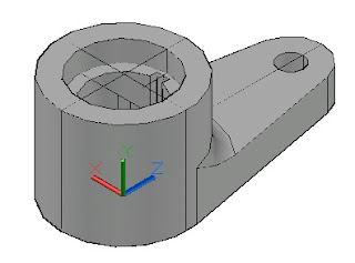
For example, we are going to convert 3d object as below to 2d drawing by using FLATSHOT command. 
The steps are as following: 
a.       Assume that firstly we are going to create 2D Drawing of Top View. So that, we have to change the view to be Top View. Go to ribbon of Visualize and choose Views menu then click Top View icon. It will appear as below.

b. Type FLATSHOT on command line, and then it will come up FLATSHOT dialog box as below.

c.       Notice that the result of 2D drawing which is going to be created will be formed as a block.
d.      Choose continuous line for foreground lines and dashed line for obscured lines. So that we can distinguish whichever visible lines (foreground line) and hidden line (obscured lines).
e.       Then click Create button. It will appear as below.

f.       On command line it also will come up :
Specify insertion point or [ Basepoint Scale X Y Z Rotate ] :
Type B and specify basepoint. Assume we choose center point of the circle as basepoint (point number 1 as following picture).

g.       After that on command line, it becomes :
Specify insertion point :
Assume the insertion point is on the point of number 2 (it also on the center point of circle solid)
h.      Then the instruction on command line is :
Enter X scale factor <1> :
Just press Enter, as we choose the scale factor is 1 as default.
i.       Enter Y scale factor <1> :
Just also press Enter.
j.      Specify rotation angle <0> :
Just press Enter.
k.      Finally we get 2D Drawing of Top View on XY plane.
l.    With the same step,let you create 2D drawing of Front View and Right Side View.


m.  On SW Isometric View (ribbon Visualize – Views menu and SW Isometric icon) it will appear this following.

n.    If we hide the layer of 3D object, it will appear this following.

o.       We have to separate it to become as below.

p.   Arrange the composition with multiple operation like Rotate3D, Move, etc. so that it becomes as below.

q.       On Top View :

r.   Notice that each of views are blocks. So that we can edit individually as block editing, such as change line type scale of dashed line.  Finally after block editing we can get 2D projection as below.

s.  We can add center line, dimensions, and text to complete this 2D drawing. So that finally we result 2D projection drawing as follow inally after block editing we can get 2D projection as below.

It is very easy, right? May be useful !!

Click other links below to learn some other methods to convert 3D drawing to 2D drawing in AutoCAD :

SOLPROF

- VIEWBASE


Bila anda ingin mengikuti Kursus AutoCAD, Solidworks, Mastercam, SketchUp, Rhinoceros 

silakan menghubungi Vector Impruva Training di :

- No telp 08118801647

- Email : vectorimpruva@gmail.com

- Alamat : Jl. Udayana IV no. UE/4 Cluster Udayana, sebelah Perumahan Bumi Indah 5, Pasar Kemis, Tangerang, Banten


Biaya Kursus Murah. Sudah Mendapatkan Sertifikat.


Menerima Pendaftaran Peserta Kursus AutoCAD, Solidworks, & Mastercam, bagi Karyawan, Profesional, Mahasiwa, dan Pelajar di Tangerang : Kelapa Dua, Gading Serpong, Karawaci,  Legok, Serpong, Islamic Village, Medang, BSD, Alam Sutera, Binong, Bonang, Cikupa, Curug, Citra Raya, Jatake, Manis, Bitung, Jati Uwung, Pasar Kemis, Rajeg, Cengkareng, Batu Ceper, Balaraja, Cibadak, dll.


Tempat Training / Kursus AutoCAD, Solidworks, & Mastercam Di Tangerang, 08118801647.

SOLPROF TO CONVERT 3D DRAWING TO 2D DRAWING IN AUTOCAD

For example, we are going to create 2D projection drawing of this following 3D object with SOLPROF. 

The steps are as following :
a.       First of all you go to Layout space.

b.       Then type MV or MVIEW on command line to create a window viewing of Model space.
c.      Then it is coming up the instruction:
Specify corner of viewport :
d.       Actually you ask to make a rectangle as a window. So that in this step you click the position of a corner.
e.      And then when coming up the instruction :
Specify opposite corner  :
You click the position of an opposite corner.
f.      Then it will appear a window that view Model space actually.
g.        Type MS or MSPACE.
h.       Notice that right now you can either zoom or show other view such as top view, front view, etc inside the window of Model space.
i.      Actually we will create 2D projection conforming to the view.
j.    Assume firstly we are going to create 2D projection of Top View. Then change the view to become Top View. On Visualize ribbon you go to View icon, and then click Top View. Eventually Top View appears. You zoom proportionally so that you can show Top View of 3D object properly as below.
k.       Then you type SOLPROF on command line.
l.      It will come up the instruction :
Select object :
You select all 3D objects you want to make its 3D drawing by clicking the 3D objects, then press Enter.

m.       It will come up the instruction :
Display hidden profile on separate layer :
Choose Yes (Y).
n.      It will come up the instruction :
Project profile lines onto a plane :
Choose Yes (Y).
o.       It will come up the instruction :
Delete tangential edges :
Choose Yes (Y).
p.      Then actually the 2D drawing of Top View has been created on Model space.
q.      With the same steps as above, let you create 2D drawing of Front View and Right Side View.
So you must change view to be Front View, then type SOLPROF, etc. Likewise for Right Side View.


r.       After you have completely created Top View, Front View, and Right Side View, you go back to Model space.
s.      Through SW Isometric View, it will appear as below.

t.    Let you hide the layer of 3D object. Then it will appear as below. Look that actually has been created 2D drawing of Top View on XY plane, Front View on ZX plane, and Right Side View on YZ plane.

u.       You have to separate those 2D drawing as below.

v.   Then you arrange with the multiple commands such as Rotate3D, Move, etc. so that it will appear the composition as below.


w.       Notice that when 2D drawing has already been created, the new layers has also been created. Let you check it out on the Layer manager. You see that 2 layer have been created with unique names. One layer is with initial name PV and other layer is with initial name PH. PV is the layer that contains 2D drawing of visible objects of 3D objects. And PH is layer that contains 2D drawing of hidden objects of 3D objects.
x.      After that you can explode the objects of PH layers and change the line type with dashed type as commonly for hidden objects. Then you can add center line, dimensions, and texts as you need.
y.   Finally you get the 2D projection drawing as below.

What do you think ? It’s easy, right ?
Let you practice it !

Click other links below to learn some other methods to convert 3D drawing to 2D drawing in AutoCAD :

- VIEWBASE

FLATSHOT


Bila anda ingin mengikuti Kursus AutoCAD, Solidworks, Mastercam, SketchUp, Rhinoceros, 

silakan menghubungi Vector Impruva Training di :

- No telp 08118801647

- Email : vectorimpruva@gmail.com

- Alamat : Jl. Udayana IV no. UE/4 Cluster Udayana, sebelah Perumahan Bumi Indah 5, Pasar Kemis, Tangerang, Banten


Biaya Kursus Murah. Sudah Mendapatkan Sertifikat.


Menerima Pendaftaran Peserta Kursus AutoCAD, Solidworks, & Mastercam, bagi Karyawan, Profesional, Mahasiwa, dan Pelajar di Tangerang : Kelapa Dua, Gading Serpong, Karawaci,  Legok, Serpong, Islamic Village, Medang, BSD, Alam Sutera, Binong, Bonang, Cikupa, Curug, Citra Raya, Jatake, Manis, Bitung, Jati Uwung, Pasar Kemis, Rajeg, Cengkareng, Batu Ceper, Balaraja, Cibadak, dll.


Tempat Training / Kursus AutoCAD, Solidworks, & Mastercam Di Tangerang, 08118801647.


VIEWBASE TO CONVERT 3D DRAWING TO 2D DRAWING IN AUTOCAD

For example, we are going to convert 3d object as below to 2d drawing by using VIEWBASE command.. 
Before we start to use VIEWBASE command, we need to set up the projection type.
So on the command line, let you type VIEWSTD and then click Enter.

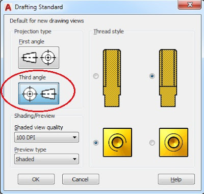
It will appear dialog box of DRAFTING STANDARD as below :

If you usually use American projection type, then you choose projection type of Third angle.
If you usually use European projection type, then you choose projection type of First angle.
Ok, for this example let us choose First angle.
Then click OK button.

After that we are going to begin VIEWBASE command.

The steps are as following :
a.       Type VIEWBASE on command line.
b.       Then it is coming up the instruction:
Specify model source [Model space File] <Model space>:
c.      Just click Enter on the keyboard as the model source is from Model space.
d.       Then it is coming up the instruction:
Select objects or [Entire model] <Entire model>:
e.      Select some objects if there are only some objects of the entire objects on model space which are selected. Or just click Enter on the keyboard if we select entire objects on model space.
f.      Then it is coming up the instruction:
Enter new or existing layout name to make current or [?] <Layout1>:
g.      Type the new layout name if necessary, or just click Enter on the keyboard if Layout1 is the layout name.
h.     Then notice that it goes to Layout1 space. And notice on the menu bar it appear toolbar of viewbase command as below and then you set up the icons that are inside the red circle marking as below.


i.       Just click Enter on the keyboard, then it is coming up the instruction:
Enter a view creation option [Base only base and Projected] <Base and Projected>:
j.      Just click Enter on the keyboard as we want to display base and projected view, then it is coming up the instruction:
Specify location of base view or [Type sElect Orientation Hidden lines Scale Visibility] <type>:
k.       Notice that the cursor is directly change into the base view. Then position it to the proper place and click left button of mouse.


l.       Then it is coming up the instruction:
Select option [sElect Orientation Hidden lines Scale Visibility Move eXit] <eXit>:
m.      Just click Enter on the keyboard.
n.       Then it is coming up the instruction:
Specify location of projected view or<eXit>:
o.      Then position cursor on the screen as either top view or right view or other views and click left button of mouse.


Then position cursor to make top view and click left button of mouse.


p.       Finish the step by clicking Enter on the keyboard.
q.    The 2d drawing finally appear on the layout1 space.


r.  And then you can complete it with dimensions and text to finish it all.


It’s very easy, right? Let you try it.

Click other links below to learn some other methods to convert 3D drawing to 2D drawing in AutoCAD :

SOLPROF

FLATSHOT


Bila anda ingin mengikuti Kursus AutoCAD, Solidworks, Mastercam, SketchUp, Rhinoceros 

silakan menghubungi Vector Impruva Training di :

- No telp 08118801647

- Email : vectorimpruva@gmail.com

- Alamat : Jl. Udayana IV no. UE/4 Cluster Udayana, sebelah Perumahan Bumi Indah 5, Pasar Kemis, Tangerang, Banten


Biaya Kursus Murah. Sudah Mendapatkan Sertifikat.


Menerima Pendaftaran Peserta Kursus AutoCAD, Solidworks, & Mastercam, bagi Karyawan, Profesional, Mahasiwa, dan Pelajar di Tangerang : Kelapa Dua, Gading Serpong, Karawaci,  Legok, Serpong, Islamic Village, Medang, BSD, Alam Sutera, Binong, Bonang, Cikupa, Curug, Citra Raya, Jatake, Manis, Bitung, Jati Uwung, Pasar Kemis, Rajeg, Cengkareng, Batu Ceper, Balaraja, Cibadak, dll.


Tempat Training / Kursus AutoCAD, Solidworks, & Mastercam Di Tangerang, 08118801647.